User Guide @Mar 10, 2010 11:39:05 AM
Interface Overview
What you see (Screen Layout)
Application and Login info
The window title holds the application and login information.
Basic Operations
Viewer Toolbar
Flight Selection Panel
This window contains a scrollable list of flights of the current flight set.
Calculations
Track Statistics
Track Density
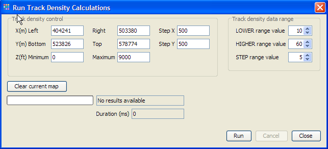
The Track Density button is used to open the Track Density calculation dialog. The calculation is done using the current set of flights. The track density results represent the number of flights passing through a grid-cel; the results are expressed as percentages of the current set of flights.
The Track density control part defines the grid area. The initial values represent the current visible part of the map at the time when the dailog was opened. These values can edited. The Z value filters in which height interval the density values are calculated. The X- and Y-values define the dimensions of the grid. Step X and Y defines the gridcell size in meters. To start the calculate press the “Run” button
Viewing the Track Density results
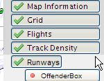
In order to view the track density result the “Track Density” layer must be enabled in the “Control Area”.
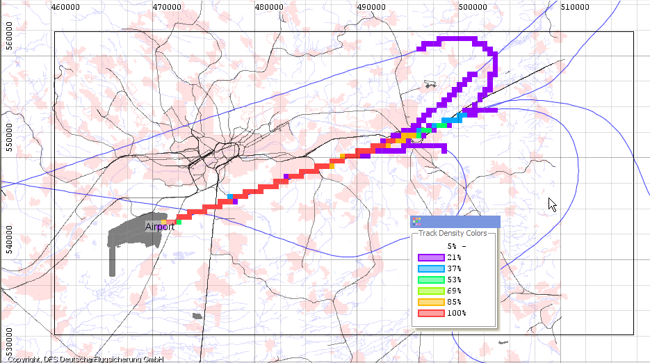
The grid area is marked with a black rectangle, and there is an extra Track Density Colors window added.
Using the controls in the “Track density data range” in the dailog the on screen picture can manipulated.
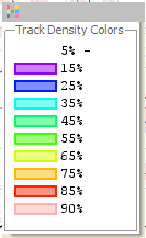
The LOWER, HIGHER range value (in percent) defines the visible interval range. The STEP range value defines the percentage step before change the color. The number of color intervals as calculate as follows; (HIGHER-LOWER)/STEP rounded up.
For example the shown color legend is the result of LOWER value 5, HIGHER value 90 and STEP value is 10. The first “purple” band show the density 5%-15%. Only the last color can have a smaller range due to rounding issues.
To clear the current density the “Clear Current Map” button can be pressed.


